Engineered CDU systems for high-density compute.
CDU skids, direct-to-chip cooling, and immersion platforms — from 300kW to 20MW+, designed, integrated, and delivered for OEMs and operators.
How CDU Systems Integrate
A closed liquid loop links facility cooling, the CDU, in-row distribution, and the racks — moving heat from compute back to facility heat rejection.
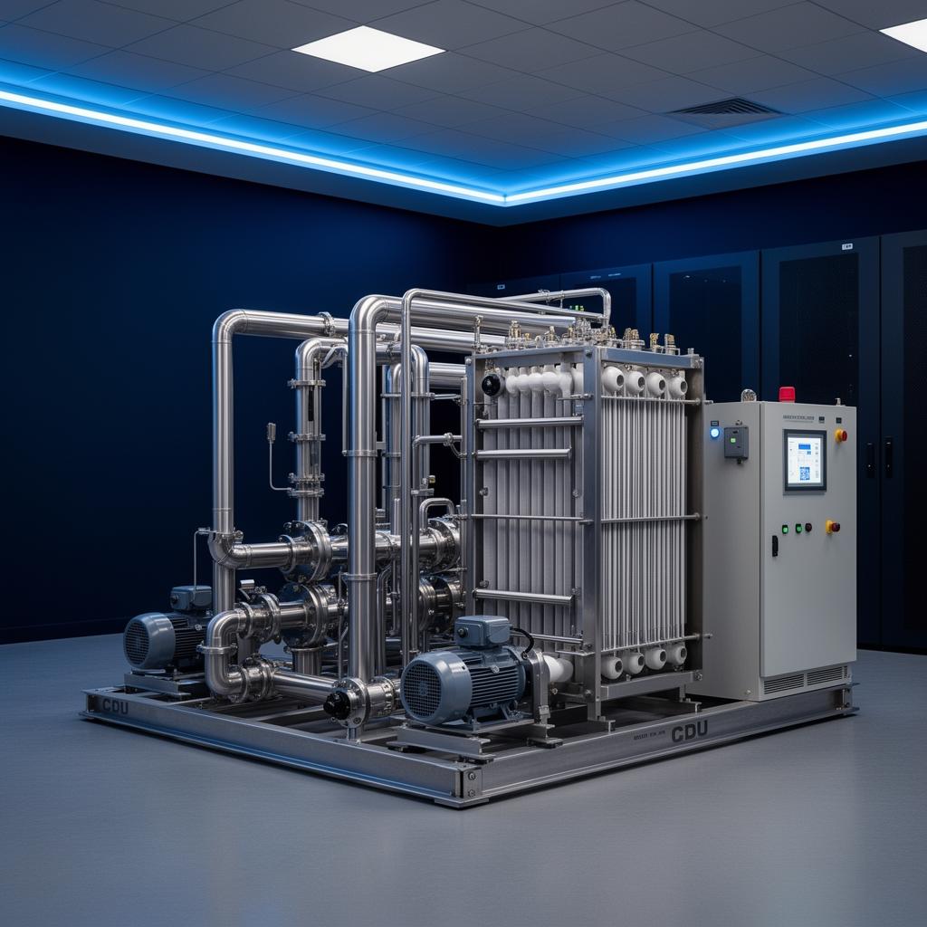
CDU Systems
Coolant distribution units engineered, fabricated, and tested as complete skid systems. From facility-water-to-IT loops at 300kW to multi-megawatt deployments serving high-density AI compute halls.
- Skid-mounted, factory built and tested
- Single-pump and N+1/N+2 redundant configurations
- BACnet / Modbus / SNMP integration
- Carbon steel, stainless, and hybrid construction
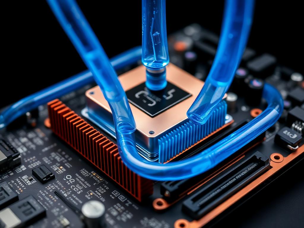
Direct-to-Chip Cooling
Cold-plate-based direct-to-chip cooling components and assemblies. Manifolds, quick-disconnects, hose runs, and rack-level distribution for current and next-generation accelerators.
- Rack manifolds and quick-disconnect couplings
- Cold plate compatibility across major CPU/GPU sockets
- Drip-free maintenance configurations
- Glycol and water-based fluid compatibility
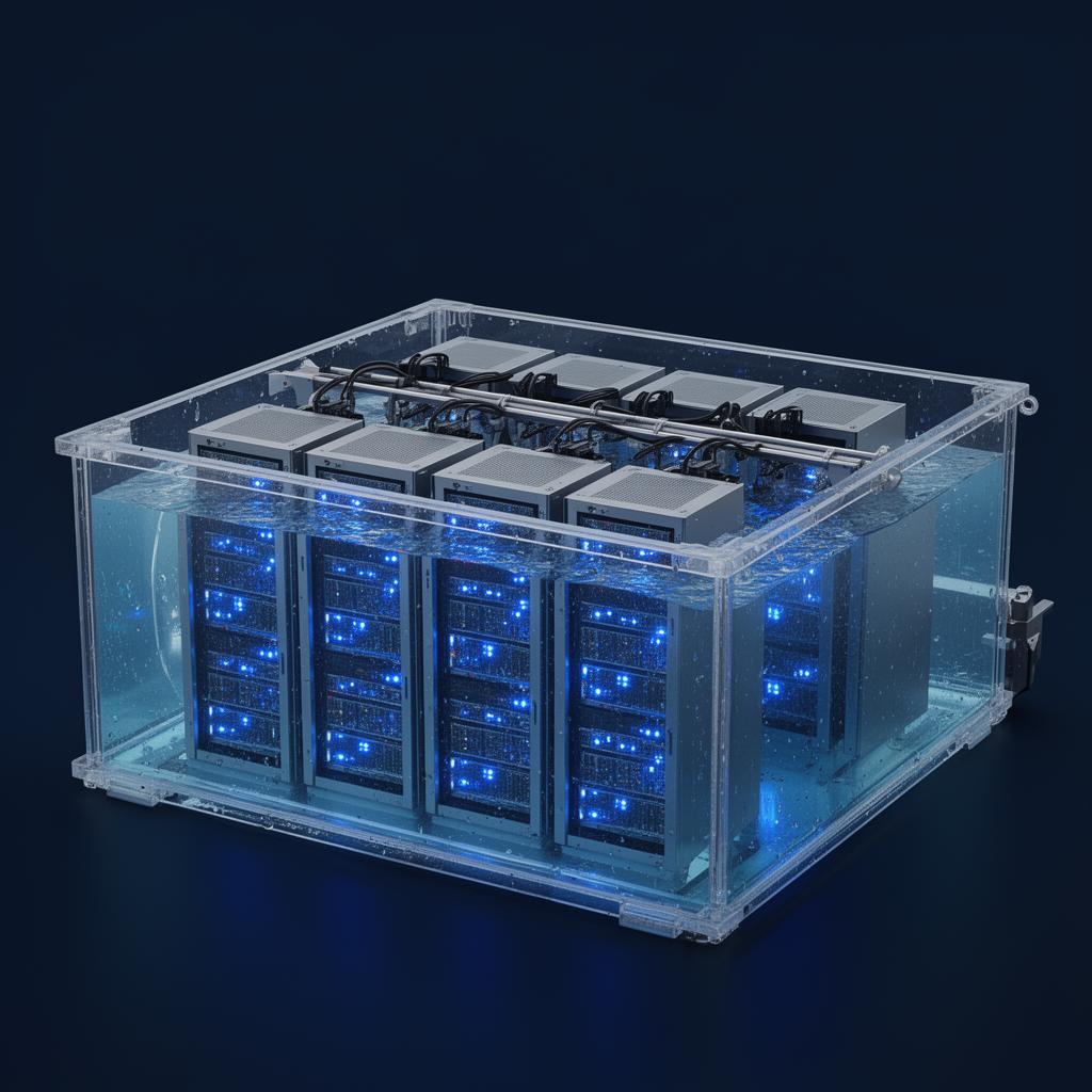
Immersion Cooling Systems
Single-phase and two-phase immersion cooling platforms. Tank systems, dielectric fluid handling, filtration loops, and heat rejection — built to support extreme rack densities.
- Single-phase (1P) and two-phase (2P) configurations
- Dielectric fluid handling and polishing loops
- Condenser and heat rejection integration
- Sensor, monitoring, and controls infrastructure
How CDU Systems Work
A CDU isolates the IT-side coolant loop from the facility water loop, exchanging heat through a liquid-to-liquid heat exchanger while controlling flow, pressure, and chemistry on the technology side.
Heat Capture
Cold technology coolant enters cold plates or immersion tanks, absorbing heat directly from CPUs, GPUs, and accelerators.
Heat Transfer
Warm coolant returns to the CDU, where a brazed-plate heat exchanger transfers thermal energy to the facility water loop.
Heat Rejection
Facility water carries heat to the chiller plant, dry cooler, or cooling tower, while conditioned coolant recirculates to the racks.
Configured for your topology
Every CDU deployment is tailored to redundancy targets, hydraulic load, facility heat-rejection strategy, and BMS protocols.
Redundancy Architecture
Mission-critical availability with engineered fault tolerance.
- ›N, N+1, N+2 configurations
- ›High availability design
- ›Concurrent maintainability
Pumping Systems
Hydraulic delivery sized to load, optimized for efficiency.
- ›Single vs dual pump options
- ›Variable speed (VFD) control
- ›Pressure-independent flow
Heat Rejection Integration
Compatible with any facility-side heat rejection topology.
- ›Chiller plant integration
- ›Dry cooler compatibility
- ›Cooling tower interface
Controls & Monitoring
Open-protocol BMS integration and full system telemetry.
- ›BACnet / Modbus / SNMP
- ›Integrated PLC + HMI
- ›Remote monitoring & alarms
+ TECHNICAL ARCHITECTUREView Detailed CDU Cooling Loop ArchitectureEXPAND
Dual-loop closed system
Heat moves from the IT-side cooling loop into the facility water loop through a heat exchange interface.
Discuss Your CDU System Requirements
From 300kW skids to multi-megawatt deployments, we design and deliver complete CDU systems tailored to your application.